
In modern industrial production, choosing the right automated joining process determines your overall plant efficiency, operational costs, and product durability. Manufacturers expanding their metal fabrication capabilities often face a crucial decision: robotic MIG welding versus a dedicated spot welding robot.
While both systems rely on high-precision industrial robot arms to eliminate manual bottlenecks, they operate on completely different metallurgical principles. A robotic MIG welding setup uses a continuous wire electrode and shielding gas to form unbroken, structural seams. Conversely, spot welding uses localized electrical resistance and mechanical pressure to fuse overlapping metal sheets without filler wire. Selecting the wrong platform can cause long cycle times, weak structural integrity, and unnecessary capital expenditure.
This guide provides an engineering-level breakdown of both technologies. We examine core mechanics, joint strength, production cycle time, equipment costs, and integration requirements so you can deploy the ideal robotic welding cell on your plant floor.
Understanding Robotic MIG Welding Systems
Core Mechanics of the Arc Welding Robot
Robotic Metal Inert Gas (MIG) welding—a specialized category of arc welding robot applications—uses a continuous consumable wire electrode fed through a welding torch. An electric arc forms between the wire tip and the base metal workpiece, generating heat to melt both materials into a shared weld pool. Simultaneously, an inert or active shielding gas (such as Argon or CO2 mixtures) flows from the nozzle to isolate the molten pool from atmospheric contamination.
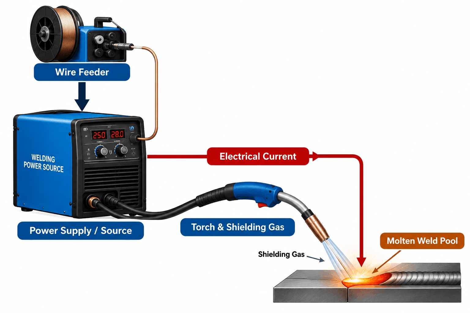
A complete system requires a specialized welding power supply, dynamic wire feed units, a water- or air-cooled torch package, safety enclosures, and advanced torch alignment sensors.
Advanced Seam Tracking and Process Control
Unlike fixed automated tools, an advanced arc welding robot must adapt to part variations in real time. Thermal expansion, laser cutting tolerances, and stamping irregularities cause slight gap shifts along joint seams. To compensate, modern systems integrate automated seam tracking technology:
- Through-Arc Seam Tracking (TAST): Measures real-time electrical impedance variations during torch oscillation to keep the robot centered on the joint.
- Optical/Laser Triangulation Sensors: Scans the joint geometry millimeters ahead of the arc to adjust the robot trajectory and wire feed parameters dynamically.
These technologies enable consistent weld penetration, clean bead profiles, and minimal scrap rates on complex 3D paths.
Understanding Spot Welding Robots
Electrical Resistance Mechanics
Resistance Spot Welding (RSW) operates without filler metals, shielding gases, or arc creation. Instead, a spot welding robot uses heavy pneumatic or servo-actuated copper alloy electrodes to clamp overlapping sheet metal pieces together under significant force.
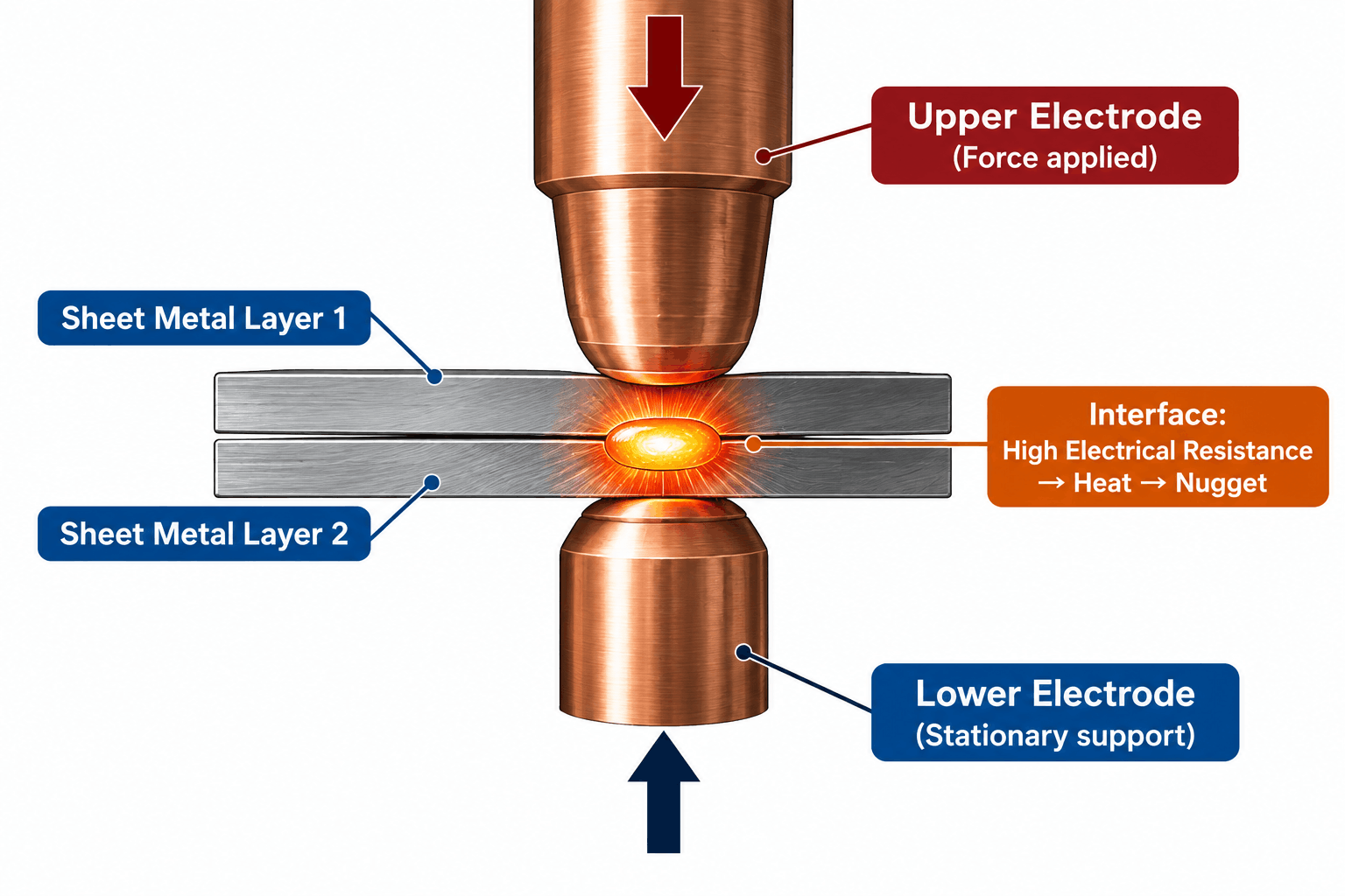
Once clamped, the integrated weld timer delivers a high-amperage electrical current through the electrodes. The natural electrical resistance at the metal-to-metal interface generates intense localized heat, melting the core metal to form a solid weld nugget as it cools under pressure.
High-Speed Cycle Automation
Because spot welding requires only short bursts of current and rapid clamping movements, it excels in high-volume production. Servo-driven spot welding guns allow the robot arm to open and close electrodes precise distances between spots, accelerating overall movement. This level of cycle automation makes resistance spot welding the standard choice for automotive body-in-white (BIW) production lines, where thousands of point welds must be placed per unit.
Direct Technical Comparison: Robotic MIG vs. Spot Welding
| Technical Metric | Robotic MIG Welding | Spot Welding Robot |
| Primary Process | Continuous electric arc with filler wire | Localized electrical resistance under pressure |
| Material Compatibility | Thick-to-thin carbon steel, aluminum, stainless steel | Thin gauge overlapping sheet metals (0.5mm – 3.0mm) |
| Joint Characteristics | Continuous leak-proof seam, high tensile load capacity | Point-based fusion nuggets, high shear load capacity |
| Seam Tracking | Required (seam tracking laser/TAST for gap variations) | Not required (depends on repeatable clamping fixtures) |
| Thermal Distortion | Moderate to high (continuous heat input) | Extremely low (localized heat pulse) |
| Cycle Speed | Slower per linear distance; continuous motion | Extremely fast per point weld (cycle speed optimized) |
| Tooling Payload | Light torch payload (10 kg – 20 kg arms) | Heavy spot gun payload (80 kg – 200+ kg arms) |
Key Decision Factors for Your Factory Floor
1. Material Thickness and Joint Design
Evaluating component geometry is the first step in system selection:
- Choose Robotic MIG Welding if your products require continuous hermetic seals (such as pressure vessels, fuel tanks, or fluid piping) or structural joints subject to multi-axis tensile stress. Continuous arc welds distribute mechanical loads evenly along the joint length.
- Choose Spot Welding Robots if your operations center on overlapping sheet metal assemblies (such as enclosures, cabinets, or vehicle body panels). Spot welding efficiently joins multi-layer thin sheet configurations without adding weight via consumable filler metal.
2. Cycle Time and Production Throughput
Production volume requirements dictate system design:
- Spot Welding Cycle Speed: A spot welding arm can execute 30 to 60 individual spot welds per minute, depending on motion pitch and metal thickness. The absence of arc-on delays and post-weld slag cleaning yields exceptional throughput for high-volume assemblies.
- Robotic MIG Welding Cycle Time: Arc welding speeds typically range between 30 to 150 cm per minute depending on parameters and wire feed rates. While individual cycle time is slower than spot welding, an optimized robotic welding cell with dual-station index positioners maximizes output by allowing operators to load and unload parts on one side while the robot welds on the other.
3. Equipment Footprint and Robot Arm Payloads
System mechanical requirements influence floor space planning:
- Arm Payload Capacity: MIG welding torches, wire feeders, and collision sensors are lightweight, allowing integration with lower-payload industrial robot arms (typically 6 kg to 20 kg capacity) with long reach capabilities.
- Spot Gun Payload: Resistance spot welding guns house heavy copper transformers, mechanical pneumatic/servo actuators, and water-cooling lines. Consequently, a spot welding robot requires heavy-duty arms rated between 80 kg and 250 kg payload capacity, which increases foundation structural requirements and floor space needs.
Total Cost of Ownership (TCO) & ROI Analysis
To calculate long-term return on investment, consider both upfront capital expenditures (CapEx) and long-term operational expenditures (OpEx).
Total Operating Cost = Consumables + Energy Consumption + Maintenance & Tooling Wear
Capital Expenditure (CapEx)
An entry-level robotic MIG welding cell generally has a lower initial equipment purchase cost than a heavy-duty spot welding cell. MIG systems use lighter-payload robot arms and standardized arc welding power supplies. In contrast, spot welding cells require high-payload robots, specialized high-amperage welding transformers, and heavy-duty mechanical clamping fixtures.
Operational Expenditure (OpEx)
- Consumables: MIG welding involves ongoing expenses for wire spools, shielding gas bottles or bulk tanks, contact tips, gas diffusers, and nozzles. Spot welding eliminates wire and gas costs entirely, requiring only periodic copper electrode tip dressing and replacement.
- Energy Demand: Spot welding draws high spike current during brief weld pulses, requiring stable plant electrical infrastructure. MIG welding draws lower, continuous power throughout the welding duration.
For detailed industry standards on weld strength testing and resistance welding guidelines, consult the American Welding Society (AWS) standards documentation and technical resources on IEEE Industrial Automation frameworks.
Integrating Your Automated System with Mahajan Automation
Deploying a automated system requires comprehensive engineering—from initial weld reach simulations to turnkey cell integration. Selecting hardware without proper process validation can lead to quality bottlenecks and poor equipment utilization.
At Mahajan Automation, we design custom industrial automation solutions that maximize floor productivity and process repeatability. Our engineering team provides end-to-end integration support tailored to your manufacturing requirements:
- Custom Cell Integration: Designing fully enclosed robotic cells with safety light curtains, pneumatic clamping fixtures, and dual-zone rotary positioners.
- Process Simulation & Reach Studies: Performing offline 3D robot simulations to verify torch accessibility, cycle times, and gun clearance before physical build-out.
- Multi-Brand Robot Programming: Expert programming for leading robot platforms (FANUC, ABB, Yaskawa, KUKA) optimized for both MIG arc tracking and spot gun servo synchronization.
- Turnkey Retrofitting & Upgrades: Retrofitting existing manual lines with automated robotic cells to scale production output without expanding facility footprint.
Explore our comprehensive engineering capabilities on the Mahajan Automation Services portfolio page, or contact our application engineers via our Automation Contact Portal to schedule a technical consultation for your plant floor.
Frequently Asked Questions (FAQs)
1. Which system offers higher overall joint strength: robotic MIG or spot welding?
Continuous robotic MIG welding typically offers higher overall tensile load capacity because it forms an unbroken metallurgical bond along the entire joint seam using filler metal. Spot welding produces localized strength at discrete nugget points, making it suitable for shear loads in sheet metal assemblies rather than heavy structural applications.
2. Can a single industrial robot arm perform both MIG and spot welding?
While theoretically possible using quick-change automatic tool changers, it is rarely implemented in high-volume production. MIG welding requires light, agile paths with high path accuracy, whereas spot welding requires heavy-payload handling for massive spot guns. Most facilities deploy dedicated cells for each application to maximize efficiency and process stability.
3. What maintenance procedures are required for a robotic MIG welding cell?
Routine maintenance includes cleaning torch nozzles, applying anti-spatter spray, inspecting wire feeder drive rolls, replacing worn contact tips, and verifying seam tracking sensor calibration. Regular inspection of torch alignment and shielding gas flow rates helps prevent weld porosity and joint defects.
4. How do I determine if my sheet metal assembly is suitable for spot welding?
Spot welding requires overlapping material layers (typically 0.5 mm to 3.0 mm per sheet) where copper electrodes can clamp both sides of the joint. If your part geometry lacks dual-sided tool access or requires a continuous liquid-tight seal, robotic MIG welding or laser welding is the better process choice.